Introduction
A particularly impressive case of self-organisation in nature comes from fireflies synchronising. A rare phenomenon, as most species don’t do it, it has puzzled scientists for decades. Recent work suggests they use extremely simple rules to do it, and the synchronising behavious emerges from the collective. What can a swarm of insects teach us about complex systems? How can we let ourselves be inspired by nature in our daily lives and interactions?

In this article, we document improving the headset prototype we previously built using a Raspberry Pi 3 and the WS2801B LED strip, by upgrading to RPi Zero W and including a Real-Time Clock module, as well as the process of designing and implementing software inspired by the behaviour of these fireflies.
This article is part of a series describing my collaboration with Hillary Leone on Synch.Live. To summarise, Synch.Live is a game in which of groups of strangers try to solve a group challenge, without using words. We will use a specially-designed headlamp, simple rules and a just-published algorithm to create the conditions for human emergence. A discussion about emergence and the goals of the project is in a previous article.
Inspiration: Fireflies in nature
It has been known for a while that fireflies produce a chemical reaction inside their bodies that allows them to produce light, called bioluminescence. Each firefly controls when the chemical reaction begins and ends. Most species of fireflies appear to use this for mating, but in a rather individual fashion. Of the thousands of species of fireflies known to biologists, it’s expected that less than 1 percent actually synchronise.
So how do they do it? For a while, the theory was that the individual fireflies synchronise with a leader. But this theory created more problems than it solved: how was this leader chosen? How do the fireflies achieve consensus?
Back in 1992, Moiseff and Copeland at University of Connecticut (UConn) decided to set out and solve this problem by researching a species of synchronising fireflies native to their area. Years later, after they set up experiments with real fireflies in false environments, and used LED lights to simulating the behaviour of a swarm in order to see how the real fireflies interact with it, the scientists were able to produce a number of very interesting insighs. Of those insights, two have directly inspired the implementation of today’s project:
- each firefly has an internal clock, which allows them to blink periodically
- whenever a firefly sees another flash, they ‘nudge’ their internal clock forward, shortening the current period, but returning to the same periodicity afterwards
And it seems that these two simple rules are enough to allow a large number of fireflies to synchronise. To see this effect in action, check out this web simulation made by developer Nicky Case.
So in a way, fireflies are like out-of-phase oscillators, which synchronise their phase with each other. Each individual performs very simple rules, but the collective result displays the emergent behaviour. It’s quite beautiful. Below is one of the videos produced by the UConn research team:
Our goal is to implement a similar behaviour in our headsets. Just like fireflies, we have autonomous devices that blink using their own internal clocks.
Our headsets do not interact with each-other as of now, unlike the fireflies. Our first goal is to see if we can get them to synchronise at all. We have already build a headset in part 2 of this series, and we aim to build another with better hardware and see if we can get their lights to blink in sync.
The Kit
To ensure that synchronisation is possible, we first must make sure that all RPis running the headsets must be able to synchronise clocks and measure time without drifting. For this, we chose to add a Real Time Clock (RTC) module to our design, which is a type of hardware clock powered by a separate battery. RTC maintains the correct time even as the Pis are off.
For the improved headset, we use the following parts:
- a Raspberry Pi Zero Wh with a case
- a Real-Time Clock module (and a CR2032 battery)
- a WS2801 LED strip with at least 30 LEDs
- a portable battery of at least 1000mA
- a USB to barrel plug cable
- a hat
- tape, or zipties, or a sowing kit
We may also need the following tools at various times in the build:
- soldering iron, solder, and flux
- a needle
- extra lengths of wire
- multimeter, to check wiring
- a stopwatch
System design
Hardware
Unlike our previous prototype, we wish to make this headset more portable, and to reduce wires as much as possible. We will be using a hat with a brim so that both the RPi and the battery can rest on the brim.

The lights on the hat have two purposes, depending on the angle they are meant to be observed from.
🟡 Crown lights, (currently in yellow) found along the brim of the hat, which can be seen from the ground level, by all the other people participating in the game. This required us to use 25-26 LEDs for the crown lights, instead of the previous 16. These lights will be the ones that blink and synchronise based on the players’ collective movement.
🟢 Pilot lights, (currently in green) which can only be seen from above, and will be used by the device filming the experiment from above and performing the tracking of each player. Just in case a more complex pattern of lights is required to be seen from top-down, we will keep more than one LED on the top of the hat. In our current prototype we are using 4. At least one of these LEDs is always on, in a vibrant pure RGB colour, to allow detection and tracking of individual players’ motion.
Software
Let’s revisit the two rules that drive the behaviour of real fireflies, and consider how to reproduce the behaviour in code with two parameters: a period or frequency and a phase. If the period is the same, then the lights should synchronise when the phase is the same as well.
To test this behaviour, as well as if the hardware allows good enough synchronisation, we implement sofware on each hat which controls the LEDs and makes them turn on and off, with a fixed period and variable, random phase.
After we synchronise the clocks, we start the script on each hat at the exact same time. As the phase becomes less random, we expect the lights to blink closer and closer to each-other until they are synchronised. In the final project, the phase needs to be controlled externally over the network, but for the purposes of the current work, we shall simulate this using a local parameter.
Despite the task appearing simple, there have been a lot of hiccups, and, following the usual Catch-22 narrative of software development, I had to try a few solutions, explore the intricate ways in which they don’t work, and move on to new ones until the right balance is met.
The firefly-like behaviour requires periodicity. Is our simplest case with a fixed phase of 0, we want the lights to turn on for a certain amount of time, then to turn back off again, and to make sure there is no drift, but even implementing an accurate periodic timer turned out to be non-trivial in Python. This will be explored at large for the interested geeks in another article.
Implementation
1) Cloning the SD card
For a faster quickstart, we clone the card from the previous prototype.
On Linux, the dd command-line tool can clone any drive to an iso file. Combining dd with a tool called pv will display a progress bar as well. Using dd requires knowing disk and partition names.
With the SD card of the RPi plugged in, the commnd sudo fdisk -l lists all the disks mounted into the system. The disk of a RPI is normally called mmcblk0 and the fdisk output should look something like this:
Disk /dev/mmcblk0: 14.5 GiB, 15552479232 bytes, 30375936 sectors
Units: sectors of 1 * 512 = 512 bytes
Sector size (logical/physical): 512 bytes / 512 bytes
I/O size (minimum/optimal): 512 bytes / 512 bytes
Disklabel type: dos
Disk identifier: 0x7bbe90af

Device         Boot  Start      End  Sectors  Size Id Type
/dev/mmcblk0p1        8192   532479   524288  256M  c W95 FAT32 (LBA)
/dev/mmcblk0p2      532480 30375935 29843456 14.2G 83 Linux
The command below copies the whole disk image to the file pi.iso. As you can see there is also a neat progress bar.
$ pv /dev/mmcblk0 | sudo dd of=pi.iso
1.24GiB 00:00:12 [200MiB/s] [===========>        ] 61% ETA 0:00:45
After the copying is done, we plug in the blank SD card, and use dd to dump the image to the new SD card. fdisk -l shows the disk name of the new card is /dev/sdc/. Be very careful not to overwrite the wrong disk!
pv pi.iso | sudo dd of=/dev/sdc
This takes a while. But after it is done I can plug in the SD card to the new prototype and obtain the exact same system setup as the previous one, with everything already enabled for the LED lights to work!
Since it is a new device, as soon as it boots and joins the network, it is allocated a new IP address.
We then access it via SSH to change its hostname to player1, and perform the specific setup steps related to the RTC module described below.
In future posts we will explore the fastest way to deploy multiple devices, as well as managing SSH keys for them.
Building the headset
2) Install the RTC module
There are multiple variants for the RTC module available, but we specifically chose this model as the board can be neatly stacked with the Pi Zero W.
The RTC Pi uses the DS1307 RTC real time clock and a CR2032 battery to maintain the date and time when the main system power is not available.
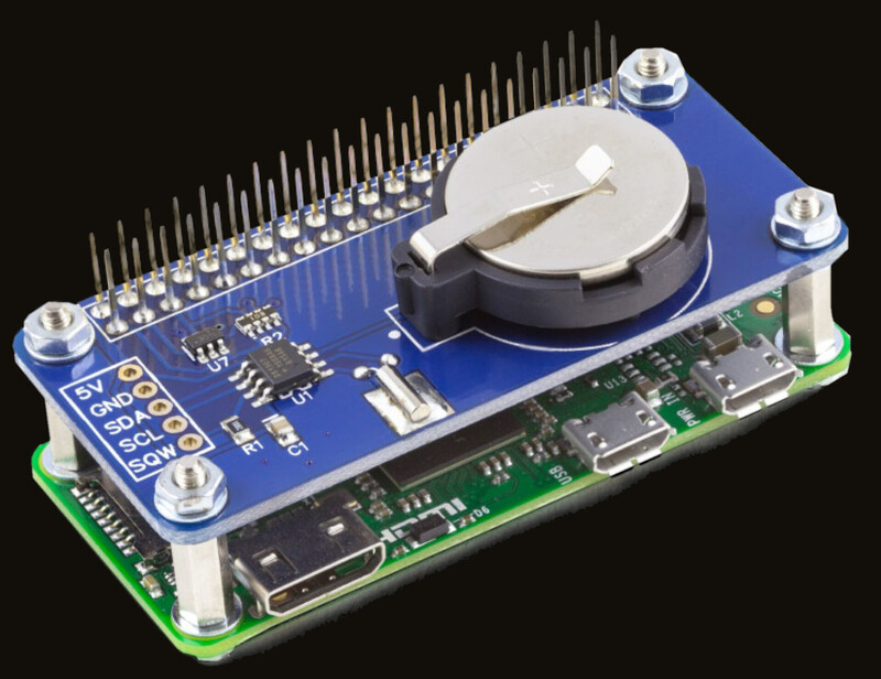
Make sure that before you plug in or turn on the Pi, the CR2032 battery is already fitted to the RTC module.
3) Lights, wiring, and power delivery
The WS2801 lights and the power cable are wired and soldered in the same way as the previous prototype. The GPIO pins for the RPi 3 used in the previous prototype are the same as the ones in the RPi Zero W used for this one.
For reference, it is replicated below, but including the RPi Zero W and the RTC module. Note that you must first put in the RTC module and only after that connect the lights. The RPi and RTC module are shown side by side below, but should be stacked as shown above:
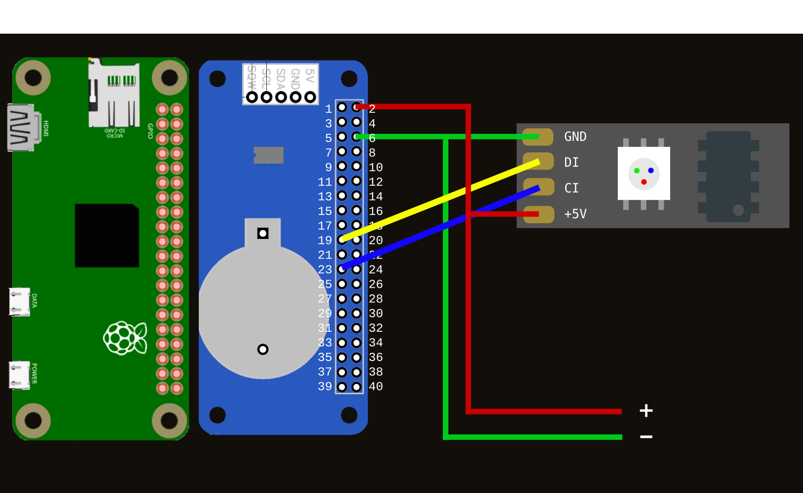
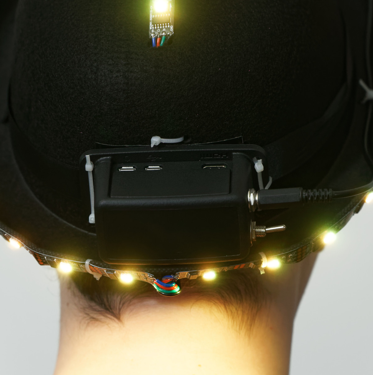
Image of the wiring and the whole setup are below:
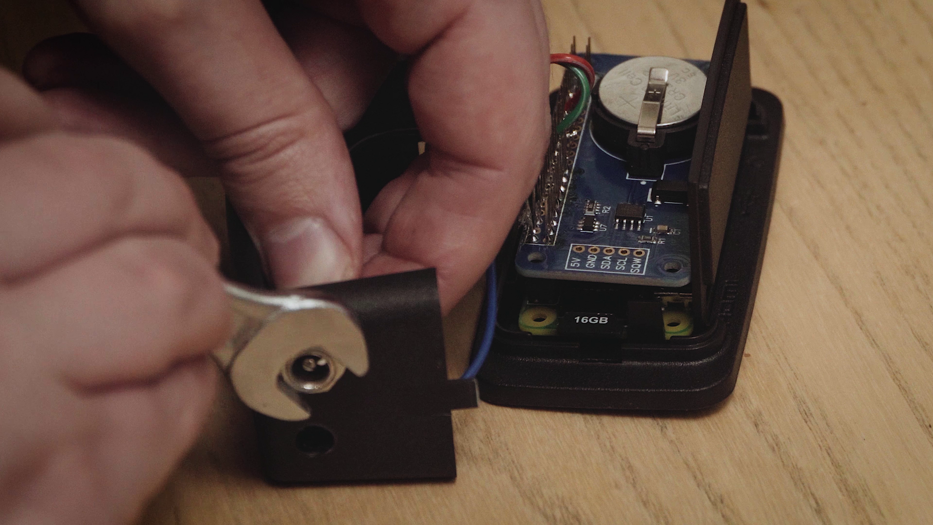
As an extra, we also included an on/off switch for the power supply. We then realised we were overzealous as one doesn’t need a switch, we can simply disconnect the power cable from the battery.
After making sure the wiring is correct and battery is in its place, we also put in the cloned SD card, and gave it power. In the previous post we have configured the system to turn on the leds and make them blink at startup, so if everything went well, then the LEDs should start blinking as soon as the system has booted.
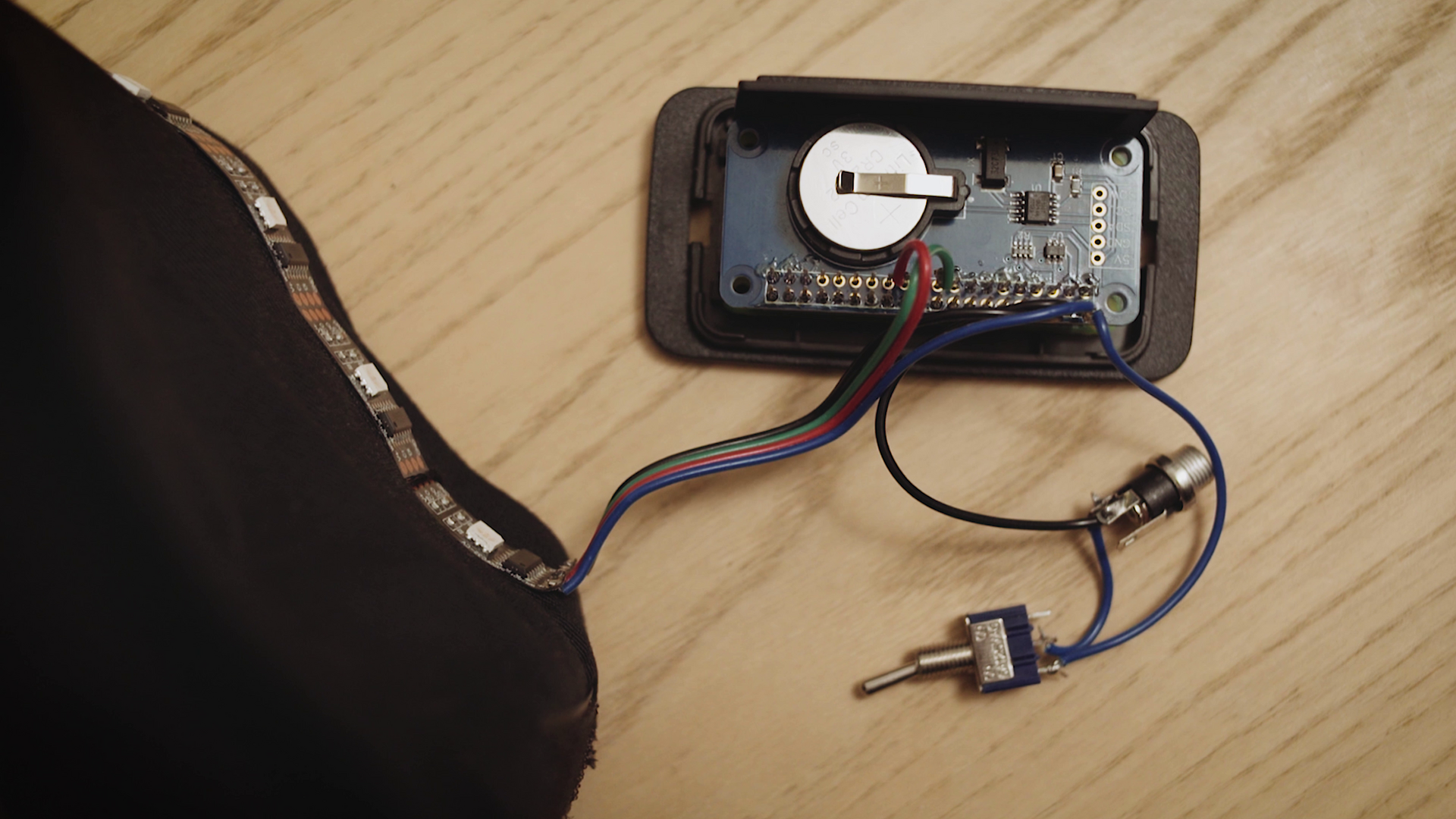
Below, a look at the final prototype, with the lights setup onto the brim of the hat. The RPi in its case rests on the back of the hat, and the battery is on the front, for balance.

Setup RTC Module
4) Enable interface and kernel module
This setup requires a little more than just running raspi-config and is documented extensively on the website of ABelectronics, from whom we bought the RTC Pi module. Some kernel modules need to be enabled as well and others removed if present.
The whole setup can be done with running the commands below.
sudo -s
# uncomment all configuration about I2C bus
sed -i "/i2c/s/#//g" /boot/config.txt
# add kernel module for DS1037
sed -i "$ a dtoverlay=i2c-rtc,ds1037" /boot/config.txt
sed -i "$ a rtc-ds1307" /etc/modules
# remove other I2C modules in case they are enabled
sed -i '/i2c-bcm2708//' /etc/modules
You should then restart the system, and check that the right modules have been enabled,
for example by printing the file /etc/modules, and making sure the following lines are present
i2c-dev
rtc-ds1307
5) install software to interface with I2C
apt-get install i2c-tools
After installing, the i2cdetect tool becomes available and can be run to check if the RTC is working. A table should be printed where the line corresponding to 60 and the column corresponding to 8 is marked in some way. This is because the address with which the RPi communicates with the module is 0x68.
$ sudo i2cdetect -y 1
     0  1  2  3  4  5  6  7  8  9  a  b  c  d  e  f
00:          -- -- -- -- -- -- -- -- -- -- -- -- --
10: -- -- -- -- -- -- -- -- -- -- -- -- -- -- -- --
20: -- -- -- -- -- -- -- -- -- -- -- -- -- -- -- --
30: -- -- -- -- -- -- -- -- -- -- -- -- -- -- -- --
40: -- -- -- -- -- -- -- -- -- -- -- -- -- -- -- --
50: -- -- -- -- -- -- -- -- -- -- -- -- -- -- -- --
60: -- -- -- -- -- -- -- -- 68 -- -- -- -- -- -- --
70: -- -- -- -- -- -- -- --
The following error may occur:
Error: Could not open file `/dev/i2c-1` or `/dev/i2c/1':
No such file or directory
One should be able to get everything working using the above, but in case not, see the bibliography at the bottom of this post for some pointers.
6) Enable the hardware clock
Next step is editing /lib/udev/hwclock-set and commenting the lines below in order to allow the hardware clock to fetch the time from the installed module and not system clock.
#if [ -e /run/systemd/system ] ; then
#exit 0
#fi
If the RPi is connected to the internet, the date and time should be setup automatically. Otherwise, you can use the date command to set them manually, and then save it by writing to the hardware clock.
sudo date -s '2020-12-20 18:35:00'
sudo hwclock -w
Now to test if this worked, make sure your RPi is not connected to the internet, turn it off, and leave it unplugged for a while. When turning it on again, the right time should be shown!
Programming the headset
7) Install Python libraries
pip3 install adafruit-ws2801 logging
We won’t use the newly added RTC module in any way in the code, but we will rely on it when using the time library to measure three second intervals, as well as for scheduling the experiment to begin at a specific time.
8) Logging
To aid with debugging, I am using the logging library and writing down the exact time, including miliseconds, of each event to a log file named by the current hostname and current date. We wish to log the precise time of each event as to measure any kind of potential drift and help development of synchrony.
The logging configuration below should be included in every file and the library will handle any issues with concurrently writing to the log from multiple files.
from datetime import date
import logging
import os
import socket

if not os.path.exists('logs'):
    os.mkdir('logs')

host = socket.gethostname()
today = date.today().strftime('%Y%m%d')

log_path = f"logs/{host}_{today}.log"
logging.basicConfig(filename = log_path, filemode = 'a', level = logging.INFO,
    format = '%(asctime)s.%(msecs)03d %(message)s', datefmt = '%H:%M:%S')
9) Operating the lights
The code uses thee Python files:
ledcontrol.py, which defines a class for the headset, and holds relevant information such as the number of LEDs on the headset, which LEDs are assigned to the crown light and which to the pilot, as well as exposes an API with the necessary functions to turn the lights on and off. The most relevant function iscrown_blink_wait.
   def crown_blink_wait(self, rand: float) -> None:
        if rand > 0:
            r = random.uniform(0, rand)
        else:
            r = 0

        logging.info(f'Waiting {round(r,3)}')
        time.sleep(r)
        self.crown_on()
        time.sleep(self.ON_DELAY)
        self.crown_off()
logger.py, which contains the code above that configures writing logs to the correct logfile, and is imported at the beginning of all the other filesmockloop.py, which creates an instance of theHeadsetclass, declares a periodic function which turns the lights on and off, as well as simulating the drift parameter decaying in order to obtain synchrony
Since the latter is only a mockup that simulates the behaviour we are looking for, I have employed a number of hacks such as using a global variable and not properly declaring a main function, which I will address in future posts as the system comes together.
The code runs a loop which calls the crown_blink_wait function periodically, and uses a Python generator to spit out time intervals corrected for any kind of drift, then makes the system sleep for the correct amount of time before turning the lights on and off again.
The code is available on github.
Synchronisation test
It’s a very exciting moment. We now have our two prototypes, player0 (on IP 192.168.1.101) and player1 (on 192.168.1.102), up and running, and present on the network, as nmap shows when scanning the local network nmap 192.168.1.1/24.
The code above has been developed onto the first prototype headset, and copied off onto the second when cloning the card. By allowing them to connect to the internet, we have also made sure they have the same clock.
I also needed to SSH into player1 and reconfigure the default values for the indexes of the LEDs, as the first prototype uses 20 LEDs but the second uses 30.
Now let’s run a synchronisation experiment. This is a qualitative experiment first and foremost, to show us whether the naked eye can notice them become in sync just like it notices the fireflies.
We can schedule the script mockloop.py to start running at a certain time, and then observe how the mock parameter rand we have coded in mockloop.py affects the randomness of blinking.
To do this scheduling I use cron, a system present in most Linux distributions including Raspbian, by running the crontab -e command and adding the following text in the prompt (which means to start the script every hour sharp):
$ crontab -e
0 * * * * python3 /home/pi/mockloop.py
More about cron in this post.
A thought, before running this qualitative test, is that I don’t expect the synchronisation to be perfect, as the two systems are not identical. One runs a RPi 3 and must turn 15 LEDs on and off, the other a RPi Zero W, and must turn 26 LEDs on and off.
Another interesting thing to think about is the nature of the random numbers used for the blinking behaviour. It is unlikely that the same random sequence would be generated on two different devices, but it might be interesting, and useful, to use a fixed seed for the numbers that is somehow associated with the specific devices, for example through the player number, for greater reproducibility when debugging.
Alas, the result is still exciting, and makes me wonder how even more impressive seeing multiple headsets synchronise will be.
Bibliography
Andrew Moiseff and Jonathan Copeland. Firefly Synchrony: A Behavioral Strategy to Minimize Visual Clutter. Science, July 2010: Vol. 329. no. 5988, p. 181 DOI: 10.1126/science.1190421
Nicky Case. Fireflies. ncase.me/fireflies/
An article about the I2C interface, what is it used for, and how to set it up, is made available by the vendor of the RTC Pi module, ABelectronics
The setup instructions for the RTC module in this post are based also on the article by ABelectronics.
These two forum threads on the RPi forums are particularly helpful in troubleshooting any issues with I2C: 115080 74763