A Raspberry Pi LED headset
Light shows. We love light shows. So many people love light shows. From artists to hackers to ravers to marketers. From the stands at hacker conventions to the LED panels in Picadilly Circus. And what is ever better than a light show, is a wearable light show.
Today we have played with the WS2801 LED strips and a Raspberry Pi and with an evening’s worth of time and effort we have designed and built a LED headset.

This article is part of a series describing my collaboration with Hillary Leone on Synch.Live. To summarise, Synch.Live is a game in which of groups of strangers try to solve a group challenge, without using words. We will use a specially-designed headlamp, simple rules and a just-published algorithm to create the conditions for human emergence. A discussion about emergence and the goals of the project is in a previous article.
The kit
We build a headset using the following parts:
- Raspberry Pi 3
- WS2801B controllable RGB LED strip, with at least 20 LED lights and connector
- power cable for the RPi
- a power bank of 10000mA (although we expect anything more than 5000mA will do, we shall test this properly in the future)
- black gaffer tape, to make the headbands that support the lights
We may also need the following tools at various times in the build:
- soldering iron, solder, and flux
- a needle
- extra lengths of wire
- a pot, to use as support when making the headbands
- multimeter, to check wiring
The lights on the headset must fulfill two functions:
First, we need a number of blinking lights that will be visible to the other players and capable of synchronising with other devices, which we call the “crown lights”.
For the purpose of tracking the players when filming them from above, we require another light or set of lights at the top of the head, which are independent of the crown lights. We call these the “pilot lights”.
WS2801B LEDs

The WS2801B LED strip has 32 RGB LEDs lights per meter, with a distance between them of about 3cm. They usually come on a strip with pretty good adhesive and can be attached to pretty much anything. The kit also includes a 4-pin connector cable. The variant we use is also waterproof!
There are many manufacturers making these, and it doesn’t matter as long as they use the WS2801 integrated circuit, which is needed to drive each light. These can be connected in series making each LED individually addressible. The strip needs only two data pins to connect to the Pi, which will also reduce the amount of wiring and soldering. Other variants, such as 2812, or 2811, may have different wiring and use different integrated circuits.
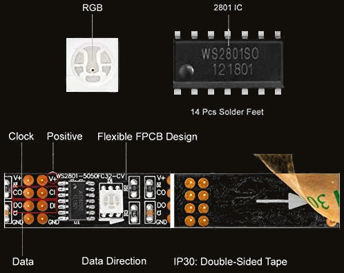
Moreover, the software package for it, made by Adafruit, allows us to specify colours in 8-bit per channel RGB for each individual LED!
Building the first prototype
Quickstart a Raspberry Pi
There are plenty of different ways of doing the same piece of setup and configuration on the Pi. For example, one can run the configuration program raspi-config, which has both a GUI and a terminal UI. But what this program does under the hood is to modify system files, which we could modify ourselves directly.
You can also run raspi-config in the command line, by passing the flag nonint for “no interactive”. Unfortunately this is not as well documented as the UI version.
In this tutorial, I will aim to present the simplest graphical way, as well as a terminal alternative that could be put into a script, for the purposes of automating it later.
Note that some configuration requires a reboot.
1) Install OS, enable SSH
We download and install Raspbian onto a MicroSD card.
Before putting the card into the RPi, first enable Secure SHell (ssh). This allows remote connections to the RPi, so we don’t need to plug in a screen, mouse and keyboard to do initial setup.
After the installation is complete, two drives will appear on the SD card. To enable ssh, simply create an empty file named ssh in the /boot drive.
Now remove the card from the PC, put it in the RPi, turn it on, and you’re ready to go.
2) Connect to network
To be able to remotely log into the newly setup Pi, it first needs to be connected to a network, but first we need to remotely log into the Pi to join any password-protected network. Chicken-and-egg problem.
Thankfully the RPi 2 has an ethernet port so we simply plug the Pi into the LAN and a wired connection requires no password.
Now to ssh into it from another machine, this machine needs to be in the same network. We also need to know its IP address, username, and password. The default username and password are usually pi and raspberry.
IP address is usually dynamically allocated by the router. The IP address we are interested in is in the local network, so by convention it’s likely begin with 192.168.
You can find it by visiting your router’s home page in the browser and looking for the list of connected devices.
I prefer to use nmap to list all devices in the network, as it is agnostic to the router manufacturer. nmap is free and available for Linux, Windows and Mac.
$ nmap 192.168.1.1/24
nmap reveals my RPi’s IP address is 192.168.1.101, and it has an open port for the SSH service, confirming that we can connect to it via SSH. ssh pi@192.168.1.101.
Normally you’d be asked to change the password on first login, and I recommend you do so. Make sure you don’t forget it!
The project will be using WiFi exclusively, so as a first step, we connect to WiFi. We can do graphically by running sudo raspi-config. Select 2 Network Options > N2 Wireless LAN, hit Enter, then enter the name of your wireless network (SSID) and then the password. You should be able to unplug ethernet now and still connect to the RPi from any computer in the same wireless network using the username, password and IP.
3) Set hostname
The default hostname for every RPi after initial setup is raspberrypi. Let’s give our RPi a new name.
To do so graphically, run the command sudo raspi-config. Select 2 Network Options > N1 Hostname, enter a new hostname, and hit Enter.
Under the hood, the system files /etc/hosts and /etc/hostname are being edited with the new hostname. I set it to be player0. The non-interactive command is:
$ sudo raspi-config nonint do_hostname player0
To check if it worked, type hostname in the terminal. If it hasn’t updated, restart the Pi and check again.
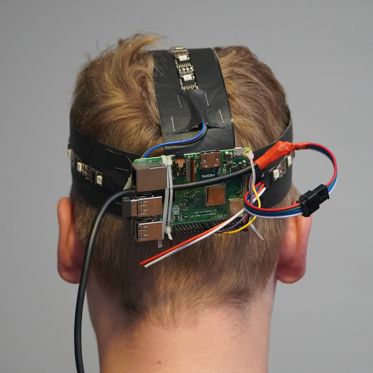
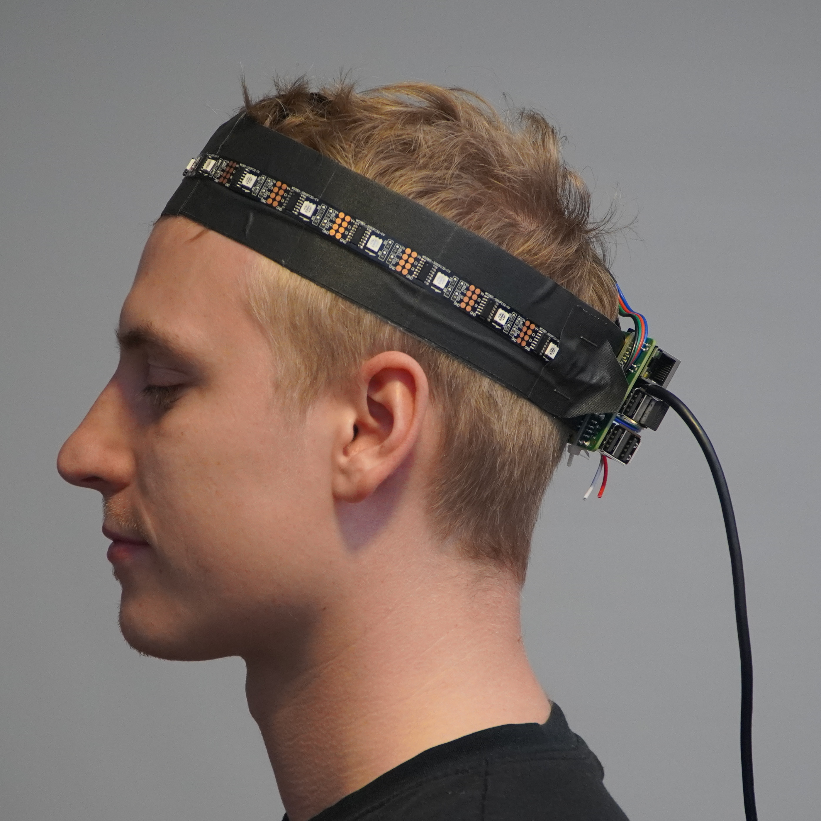
Building the headset
4) Soldering the lights
The average circomference of the adult human head allows about 15-16 of these LEDs into the crown light. We also use 4-5 LEDs to act as pilot lights. The LED strip can be cut with a scissors anywhere and soldered back again in order to allow the LEDs to be placed however and wherever we want.

We cut the LED strip after 16 lights, obtaining a strip with the power connector at one side, and again after 4 more which leaves us with a loose strip. The four golden connectors at the end of the strip can be punched with a needle and wires drawn through it, which we solder together, allowing some 5cm of wire between the two strips.
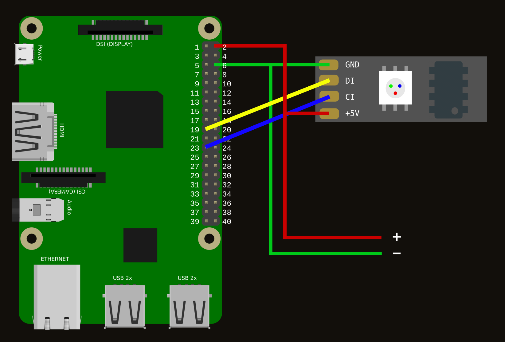
5) Wiring the lights to the RPi
Sensors and lights generally use the RPi’s GPIO (General Purpose Input/Output) interface, which offers a direct connection to the Pi’s system-on-chip. Besides data connections, some of the pins also can provide electricity, others can act as ground pins. The WS2801 LEDs will use the SPI (Serial Peripheral Interface) pins. Data is synchronised using a clock over the SCLK pin and sent from the Pi to our LED strip using the MOSI pin.
The lights have four pins:
- 5V, to be connected to + on our power supply
- GND, ground, to be connected to GND (Pin 6) on the Pi
- DI (sometimes SI), a data pin, to be wired to SCKL (Pin 19) on the pi
- CI (sometimes CK), another data pin, to be wired to MOSI (Pin 23) on the Pi
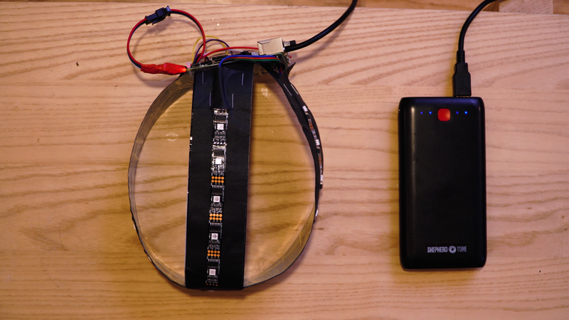
6) Power delivery
Each individual LED consumes about 60mA at DC5V. Times 20, that’s 1.2A. The GPIO of Raspberry Pi can usually deliver about 18mA by GPIO per pin, so we shouldn’t try to drive the lights, or any relevant peripherals in general, through the RPi’s power supply. A discussion about this can be found here.
Since in general the RPi’s internal power management cannot drive all the LEDs safely, we are feeding power to both the RPi and the LEDs in parallel from the same 2A rail of the power bank. Ground/earth must also be done in parralel. Now the maximum load is up to the USB output of the battery pack and not to the limits of the GPIO 5V rail.
As the RPi 2 features GPIO pins (unlike the RPi Zero W, which has holes to solder to), we can use the connector that comes with the lights and just plug them in.
Our wiring looks a little messy but it works:
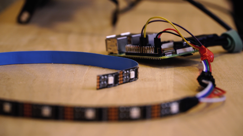
To create a headband to attach the lights and the RPi to, we use a pot and gaffer tape.
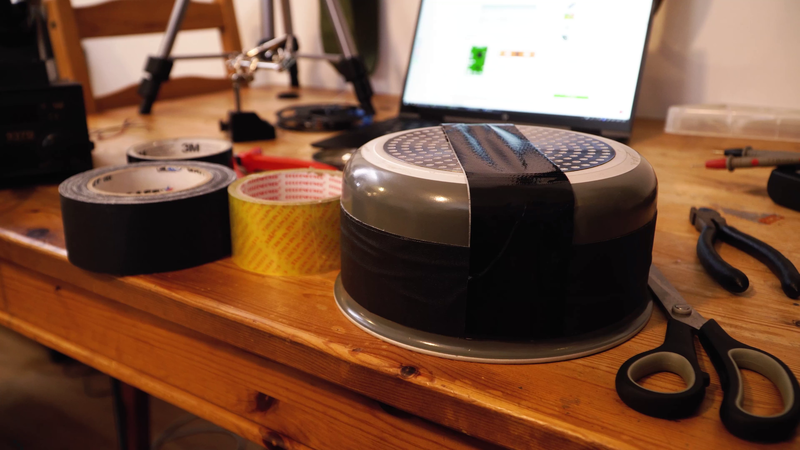
Our prototype headset looks like this:
Incorrect wiring or power delivery could fry the lights, the RPi, or both, so we have used a voltmeter to check continuity before turning it on.
Interacting with the LEDs
7) Enable SPI
To control the lights the SPI interface needs to be enabled in the OS kernel. Run sudo raspi-config, then select 5 Interfacing Options > P4 SPI and hit Enter when Yes is selected.
Under the hood, the program adds the line dtparam=spi=on to the config file /boot/config.txt.
To do it non-interactively, run:
$ sudo raspi-config nonint do_spi 0
and note that if something is enabled it will be set to 0, and 1 otherwise (weird?).
You need to reboot for this change to take effect. Afterwards, check if it worked, the lsmod command lists the kernel modules the system can detect. Something called spi should be listed there, and we can use grep to find it:
$ sudo lsmod | grep spi_
The output should list something like spi_bcm followed by some number. This means the SPI module has been enabled.
8) Install libraries
We should always begin by pulling the latest software updates, then we install the Python package manager pip and the required spidev packages for the SPI interface. The SPI packages should be already there for the version of Raspbian we are using, but let’s install it anyway just in case.
The adafruit package provides an interface for controlling the LEDs.
We are using Python3 as it supports many features we may want to use in the future iterations of this project.
$ sudo apt-get update
$ sudo apt-get install -y python3-pip python3-spidev
$ sudo pip3 install adafruit-ws2801
9) Write the code
The first step is to import the adafruit-ws2801 module as well as the GPIO module. This allows us to define a variable, leds, which is an array of RGB pixels representing each LED. Since we use 20 LEDs in our headset, we define the LED_COUNT to be 20.
import RPi.GPIO as GPIO
import Adafruit_WS2801
import Adafruit_GPIO.SPI as SPI

LED_COUNT = 20
SPI_PORT   = 0
SPI_DEVICE = 0
leds = Adafruit_WS2801.WS2801Pixels(PIXEL_COUNT,
  spi=SPI.SpiDev(SPI_PORT, SPI_DEVICE), gpio=GPIO)
Now we can use the function set_pixel, which takes two parameters, an index for the pixel number, and a colour, which we obtain by using the function Adafruit.RGB_to_color. The index 0 is the closest pixel to the connector. Every time we make a change in code to one of the pixels, you should use pixels.show(), otherwise no change will occur to the lights.
To turn of all LEDs, you can use pixels.clear()
To recreate the effect in the image at the beginning of this article, (make the lights blink twice in blue, red, and green repeatedly, while waiting a little bit in between), we can use the following code. Remember to import time at the top so we can wait during the blinks and in between blinks using the function time.sleep(seconds)
def blink(leds, col):
  leds.clear()
  for i in range(2):
    for k in range(leds.count()):
      leds.set_pixel(k,
        Adafruit_WS2801.RGB_to_color(col[0], col[1], col[2]))
    leds.show()
    time.sleep(0.1)
    leds.clear()
    leds.show()
    time.sleep(0.1)
  time.sleep(0.5)

if __name__ == "__main__":
  leds.clear()
  leds.show()

  while True:
    blink(leds, color=(0, 0, 255)
    blink(leds, color=(255, 0, 0)
    blink(leds, color=(0, 255, 0)
Let’s save all of this into a file, and call it ledcontrol.py, and put it in the home folder, /home/pi. Now we can run python3 ledcontrol.py and the LEDs will turn on!
You may play with this to your heart’s content. You can install interactive python (sudo apt-get install ipython) and put in the imports and definition of the leds variable from above, then write code and tell the lights what to do interactively. It’s pretty rewarding.
10) Run at startup
Finally, we want our script that makes the lights blink to run when the Pi is turned on without us having to run it ourselves. To do this, you can add a .desktop file to /home/pi/.config/autostart, which will tell Raspbian that our script should automatically start when turning on the system. The desktop file should have the following contents
[Desktop Entry]
Name=ledcontrol
Exec=/usr/bin/python3 /home/pi/ledcontrol.py
Type=application
Future work
As this is only a prototype, we can observe some issues with it right away. The battery is too unwieldy, and the RPi is too big. We will redo the work with a RPi Zero W, which is much smaller, and we’ll be running battery tests to see what is the smallest battery can use. In the next steps, we will also add a RTC (Real Time Clock) module to our system, and look into programming the synchronising behaviour.
Moreover, we will need to consider software for setting up and deploying a whole fleet of such headsets. From managing their hostnames to their software updates.
Bibliography
Plenty of information and instructions for this project come from the folks at tutorials-raspberrypi.com, as well as the code which inspired the GIF below.
Other resources and tutorials, such as the various ways to enable the SPI interface, are available at raspberrypi-spy.co.uk
A beautiful web interface for the pinouts of many types RPi is available here
About raspi-config noint there is little documentation, but I was able to find some hints on StackOverflow.
I shall now leave you with a last headlight delight: